A robot simulation can only be as useful and accurate as the utilized models.
This post is only concerned with geometric models, future ones will also concern kinematics.
There are many options available for each part of a worflow: CAD modeling, mesh export, mesh format conversion and mesh simplification.
In what follows I'll describe one workflow completly based on open-source components that works for me, i.e. is fast, extensive and reliable.
The targeted simulator is Gazebo (and the models also work as Markers in rviz).
One important aspect of mesh models that is often neglected are per-vertex normals (compared to mere per-face normals).
This is very unfortunate if the simulated models should be visually accurate / realistically looking - which is important if you also want to test vision algorithms with simulated sensors.
Especially for rounded objects, Phong shading based on vertex normals of the real (CSG) CAD surfaces, will look much more realistic than without.
CAD modeling
We use FreeCAD as CAD program.
It is open-source, based on a parametric CAD kernel (OpenCASCADE), supports many import/export formats and has a good Python API.
I'm not going into the process of modelling with FreeCAD here.
There are many tutorials out there.
Yet, in case you do not like the existing ones and you suppose to benefit from another one here, just drop me a note or add a comment below.
To continue, let's assume the object is modelled.
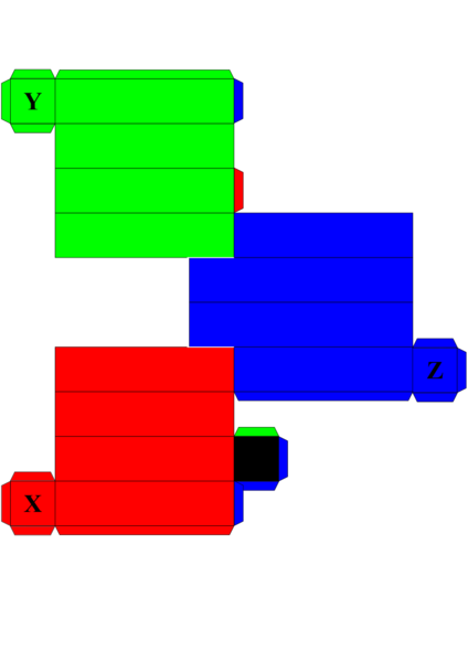
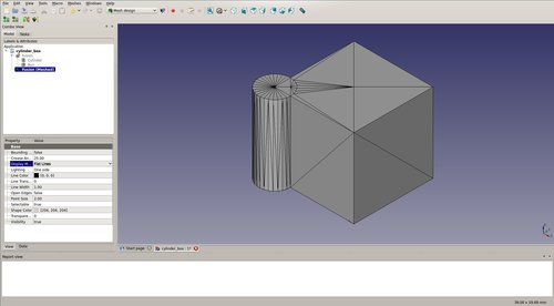
We'll use the union of a box and a cylinder (just click "Create box" and "Create cylinder" in the "Part" workbench, select both and click "Make a union" to get the example shape).
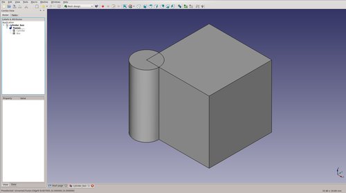 This means there is a geometrically exact representation of the object we want to use in Gazebo.
Unfortunately, most real-time graphics engines do not work with CSG, therefore we have to approximate the actual geometry by a triangle mesh.
This means there is a geometrically exact representation of the object we want to use in Gazebo.
Unfortunately, most real-time graphics engines do not work with CSG, therefore we have to approximate the actual geometry by a triangle mesh.
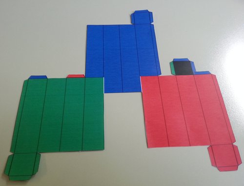
Mesh export
We can achieve this using the "Mesh design" workbench's "Create mesh from shape" function (Tessellation settings: "Standard", Surface deviation=1.0):
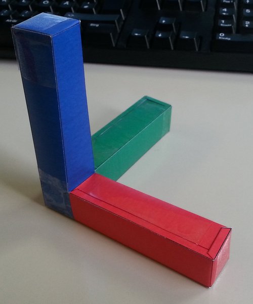
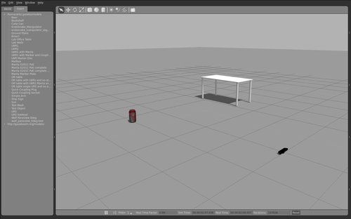
 This works well, but once we load the object into Gazebo, we recognize that the cylinder part does not look very round.
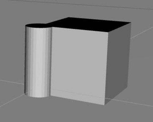 One solution would be to increase the number of triangles, i.e. decrease the "surface deviation" parameter.
Unfortunately, this goes along with a (big) rendering performance degradation.
If we only care that the objects looks to be round (in contrast to its geometry actually being rounder), we can use Gazebo's support for vertex normals and Phong shading.
One solution would be to increase the number of triangles, i.e. decrease the "surface deviation" parameter.
Unfortunately, this goes along with a (big) rendering performance degradation.
If we only care that the objects looks to be round (in contrast to its geometry actually being rounder), we can use Gazebo's support for vertex normals and Phong shading.
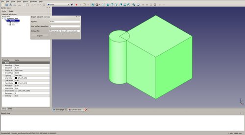
This FreeCAD macro (copy to ~/.FreeCAD/) exports FreeCAD parts together with their vertex normals as Wavefront .obj file.
It works by querying the parametric part representation for the actual normal at each vertex position.
This is completely different and superior to using a "smooth" feature (e.g. in Blender "Transform" -> "Shading: Smooth") on the mesh after export.
Note: The script is not implemented very efficiently at the moment, thus the export may take a while depending on the final mesh size.
Gazebo supports .stl and Collada. dae files, whereas the former does not at all support vertex normals.
Our exported .obj mesh can be converted to a .dae file preserving the vertex normals using this Python script:
./obj2dae.py -u cm cylinderbox.obj cylinderbox.dae
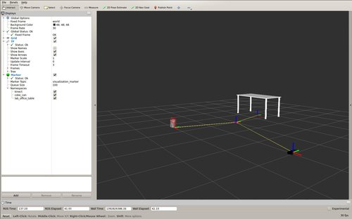
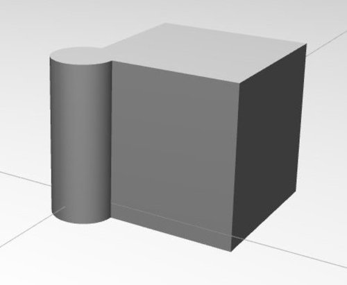
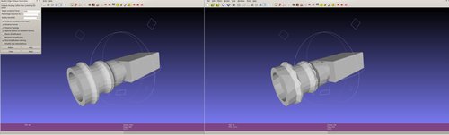
The resulting mesh is rendered much smoother in Gazebo:
Mesh materials
This post is about creating geometrically and visually accurate Gazebo models.
We have achieved geometrical accuracy through using a parametric CAD program.
Visual accuracy in relation to geometry is also given by exporting the actual vertex normals.
What is missing are proper material definitions and textures for each part of the mesh - this will be covered in a future post.
Mesh simplification
Although we avoided excessively detailed mesh geometries by substituting vertex normals for more triangles, the meshes are most likely too detailed as collision bodies.
I want to point two paths towards simplified meshes, i.e. having less triangles, to be used as SDF <collision> property.
The first is to allow higher deviations through FreeCAD's tessellation settings.
The second path is to simplify our visual mesh.
Blender has a "Decimate" modifier.
And MeshLab offers several mesh simplification techniques.
Below is an example using the "Quadric Edge Collapse Decimation", reducing the mesh faces to 1/2 of the original:
Now that we have our models, enjoy simulating.